
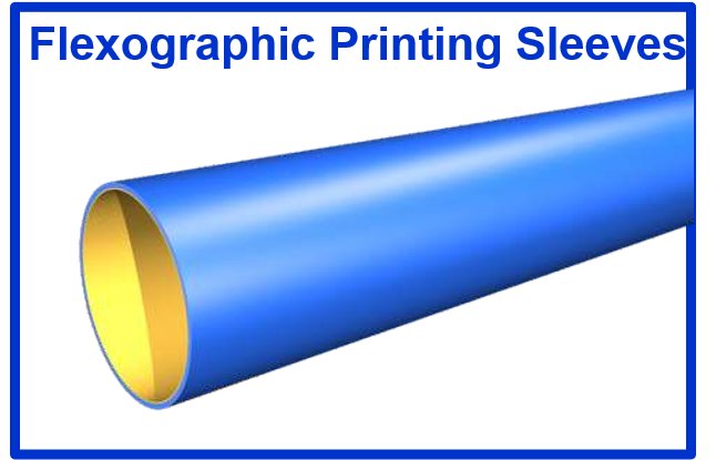
Flexographic Printing Sleeves
Sleeves Background:
Today’s Flexo Sleeves install with compressed air onto mandrels, and the printing plates are mounted onto the sleeve. Many flexo sleeves are used on conventional presses which are running Integral Cylinders, where the integral cylinder has been drilled for air passages to allow the sleeves to be used.
In addition to this market, the more recent trend in Flexographic presses is to have just one Air shaft mandrel (instead of many cylinders) that stays in the press all the time.
This mandrel accepts different diameters of printing sleeves to achieve different repeats.
These new presses are also equipped with mandrels to have the anilox roller as a sleeve. The advantage is that anilox rollers can be changed quickly also.
Understanding of Gear Pitch:
The understanding of Gear pitch, repeat length and diameter, and printing materials, is important to understanding sleeves.
- Gear Pitch in North American machines is typically 1/4CP or 10DP
- Gear Pitch in European machines is typically metric, 5mm or 10mm
Pitch Diameter is the diameter at which the teeth are engaging with the mating gear and is, therefore, the Printing Diameter. The raised parts of the Printing Plates (that apply the ink) must be equal to the pitch diameter. In practice, the raised parts of the plate are actually .002” (0.0508mm) higher than the pitch diameter, to give an “impression squeeze” when the gears are perfectly meshed.
CP is Circular Pitch – it is the distance between each tooth on the gear, as you go around the circumference. Therefore ¼ CP is a quarter inch from the tooth – to – tooth around the circumference. Likewise, 5mm pitch means that there are 5mm from the tooth – to – tooth on a metric gear.
Example:
If a ¼ CP gear has 60 teeth, we know there are 4 teeth per inch, so we have:
60 / 4 = 15 inches around the pitch diameter/printing diameter
This is a 15-inch repeat.
Example:
If a 5mm gear has 60 teeth, we know that there are 5mm per tooth, so we have:
60 x 5 = 300 mm around the pitch diameter/printing diameter
This is a 300 mm repeat, or 11.811 inches repeat
DP is Diametral Pitch – it is the number of teeth per inch of diameter. If we want to print 15 inches of repeat, we must find the closest diameter that has a corresponding number of teeth. (you can’t have a fraction of a tooth!)
Example:
15 inches repeat / pi 3.14159 = 4.775 pitch diameter.
Since the gear will have 10 teeth per inch of diameter, we have:
4.775 inches of diameter x 10 teeth per inch = 47.75 teeth.
But we can’t have a fraction of a tooth, so we can use 47 teeth or 48 teeth.
If 48 teeth are used, the pitch diameter is 48 teeth / 10 teeth per inch = 4.8 inches
The Pitch diameter is 4.8 inches, so the repeat is 4.8 x pi = 15.079
This is why presses with 10 DP gears cannot print repeats of nice round numbers like 19.75 or 23.25, they are always fractional numbers like 15.079. But the pitch diameters are always nice round numbers – say 4.800 inches – because they are always the number of teeth divided by 10!)
If we remember that the printing plate must be mounted to the cylinder so that the top of the plate is the same or .002” (0.0508mm) higher than the pitch diameter, then we have to subtract the plate thickness, and the mounting tape thickness, to find out what the Bare Cylinder Diameter must be.
The bare cylinder diameter is the outside diameter of the cylinder or sleeve that will receive the plate and tape.
Photopolymer Plate and Plate mounting tape
As Flexo quality has improved, the rubber plates have been replaced by thinner Photopolymer plates. These plates can have more detail, and they are harder, so they don’t distort as much. The thinner plates have the added benefit of allowing printers to use sleeves at the same time, to make up the difference in thickness.
This allows a printer to change from rubber to photopolymer, and keep the same gears and bare cylinder diameters. The most popular thickness of the photopolymer plates is 0.067” (we calculate using 0.065” to allow the .002” squeeze!). The difference in thickness between 0.107” plates and .067” plates is 0.040”
The importance of 0.040 inches (1.016mm)
In ¼ CP machines, each quarter-inch of repeat is equal to one tooth on the gear and is also equal to a 0.040-inch increase in the radius of the printing cylinder.
Therefore, if the printer reduces plate thickness by 0.040 inches, he has two choices: to use a gear with one less tooth or to use a 0.040 sleeve to get back to the original diameter, and then re-use the same gear.
Likewise, if a printer needs to print a longer repeat than his existing cylinder permits, he can simply buy sleeves in .040 increments of wall thickness, and only buy new gears, not entirely new cylinders.
Finally, if a printer will use both 0.107 plates and 0.067 plates, he can mix them using the above principle.
Flexo Sleeve Market:
The flexo sleeve market has several types of sleeve users, depending on what the equipment is and depending on what type of printing is being done.
Conventional Machines (Integral Cylinders drilled for air to install sleeves)
- Need for new repeats – buy sleeves and gears rather than new cylinders
- Need to accommodate new plate thickness – changing from .107 to .067
- Re-run Jobs – leave plates mounted to save the labor of demounting and remounting, and save the cost of tape on subsequent runs.
Cantilevered Machines (One mandrel stays in the machine – all jobs run on sleeves)
- Must have sleeves for each repeat
- Must consider Carrier Sleeves plus thinner allied” sleeves versus all sleeves mounting on the base mandrel (more on this later)
- If Carrier sleeves are to be used, will the carrier stay in the press while the thinner “allied” sleeve is changed?
- Concerns about Quality of Printing – a build-up of tolerances that could influence performance at high speeds or high line-count artwork
- Weight and deflection – as it relates to tolerances, bounce, and deflection.
- Weight – as it relates to operator safety and accuracy for installing sleeves on the press.
The Technology:
Sleeves are manufactured on Tooling (basically a mandrel that acts as a form). The tooling is owned by the sleeve manufacturer and is sized to correspond to popular ¼ CP, 10 DP, and 5mm and 10mm cylinders with “conventional” undercuts, such as 0.125” in the USA. The printer must check that the cylinder (mandrel) that he plans to buy sleeves for, matches the tooling of the manufacturer.
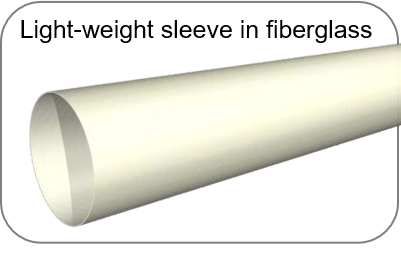
When sleeves that required a thick wall to build repeat, the manufacturers apply various Urethane compounds to achieve the correct size. Urethane very stable, lightweight, and easily machined material that also provides a fine smooth surface for Plate mounting tape adhesion. For the wall thickness over one inch, there is an extra layer of lighter material sandwiched between the fiberglass think sleeve and the Urethane outer layer.
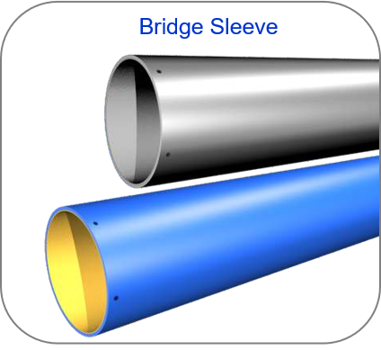
If the printers want the benefit of thinner-walled sleeves for reduced cost and weight, they can mount the thinner sleeves on a Bridge Sleeve. The “Bridge Sleeve” is not intended for direct plate mounting – Its sole purpose is to act as a bridge between the smaller mandrel and the allied sleeve at the desired repeat.
If the printers want the benefit of thinner-walled sleeves for reduced cost and weight, they can mount the thinner sleeves on a Bridge Sleeve. The “Bridge Sleeve” is not intended for direct plate mounting – Its sole purpose is to act as a bridge between the smaller mandrel and the allied sleeve at the desired repeat.
The Bridge sleeve is manufactured for lightweight and long life with the best possible tolerances. Many Bridge Sleeves are made of Carbon Fibre to achieve these goals.
The Carbon Fibre Bridge still has a base sleeve at its center, and it still requires the use of a compressible layer. It can have internal piping to deliver separate compressed air to the outer sleeve, or it can have a flow-through design. Despite the compressible layer in this sleeve, the combination of the carrier and the outer allied sleeve (with no compressible layer) is capable of reproducing very high-quality process artwork. The competing technology to this Air Mounted Bridge sleeve is a mechanically locking Carrier sleeve, which is considered by some to have an advantage due to the elimination of the compressible layer in the Bridge.
On the occasion that the Bridge Sleeve approach is not desirable because of cost or perceived loss of tolerance, sleeves can be made with a wall thickness greater than one inch, with the sandwich construction mentioned previously. These sleeves are more costly per sleeve at a given repeat than thinner sleeves. The customer must decide what is the optimal combination for his mix of production. If more than one set of sleeves is desired at a given repeat, the payback on Bridge Sleeves is fast, but the initial investment in carrier sleeves is more if the customer is not buying multiple sets.
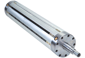
Air Shaft Mandrel base:
Sleeves are guaranteed to mount and lock on industry-standard air mandrels having a diameter tolerance of +0.0005/-0.0000” from the specified standard BCD and a maximum TIR of 0.0005” (0.0127mm)
The sleeves are guaranteed to have a TIR of no more than 0.001” with a diameter tolerance from sleeve to the sleeve of +/-0.0008” (0.02032mm)
Care and Handling – recommendations MANDRELS AND PRINT SLEEVES
Air Pressure:
- The air pressure measured at the air shaft mandrel should be between 6 & 8 bar (87-116 psi)
- The air volume should not be below 12 liters per second (0.42 cubic ft/sec)
- Please make sure air can pass freely without any difficulty.
- Unnecessarily long or branching supply lines may lead to a drastic fall in air pressure
- The compressed air system and the air cylinder surfaces should not be wet or dirty of oils, lubricants, and inks.
- Check the blockages in the air outlet from time to time.
Cleaning and storage of sleeves and mandrels:
- Care should be taken to ensure the product is stored in a way that it will not be exposed to dripping liquids including pipe condensation or leaking oils.
- Appropriate humidity levels are below 50% Humidity. Appropriate temperature levels are between 20°C and 27°C.
- The only suitable solvents for cleaning are ethanol, Isopropanol.
- Plates and tape should always be demounted after use so that solvents do not damage the sleeves
- After cleaning leave the sleeves or mandrels, to dry for about 30 minutes to allow the complete evaporation of solvents
Plate mounting:
- Mount the tape while the sleeve is on the mandrel.
- Clean the lubricant, oil, and ink residue to avoid reducing the adhesion properties of the tape.
- Use minimum air pressure to inflate the sleeve. Too much air pressure causes the bond between the sleeve and tape or the tape and plate to break. Use only enough air pressure to allow the sleeve to slide on and off.
- Sleeve surfaces vary in material type, surface roughness, and surface condition. Extra care and preparation of the surface may be necessary to achieve good bond strength.
- In order to avoid the edge lifting of the plates, adjust the tape gap and the plate gap by a minimum of 30°.
Plate Demounting:
- Remove the printing plate slowly, carefully, and with constant tension in order to avoid plate damage.
- Remove the tape by slowly pulling it back from the corner at an angle.
- The plate should be removed using a natural 90° angle.

About the Author:
Mohammed Abdul Haleem
Email: packagingprinting@consultant.com
With almost 27 years of experience in the printing industry, he offers proactive recommendations on anilox roll specifications, flexographic printing sleeves, testing, inventory management, flexographic equipment applications, training, representation from experience in technical sales, marketing, production, technical service, parts, and supplies. His experience covers the spectrum of flexographic markets including wide web flexible packaging, narrow web, tag & labels, foil, folding carton, corrugated packaging applications.